An industrial macaroni layout is not a row of machine rectangles placed inside a building outline. It is a controlled record of product flow, ingredient movement, operator routes, service access, utilities, structural limits, installation paths, and the boundary between supplied and site-provided work. Starting that record early helps the buyer and supplier resolve conflicts before equipment reaches the factory.
Zhuoheng's confirmed industrial route includes flour preparation, mixing, feeding, extrusion, forming, cutting, drying, cooling, and packing. The complete macaroni production line covers 100–500 kg/h class configurations, while exact dimensions, loads, utilities, and arrangement depend on the selected project. The layout must therefore follow an approved configuration rather than a generic capacity label.
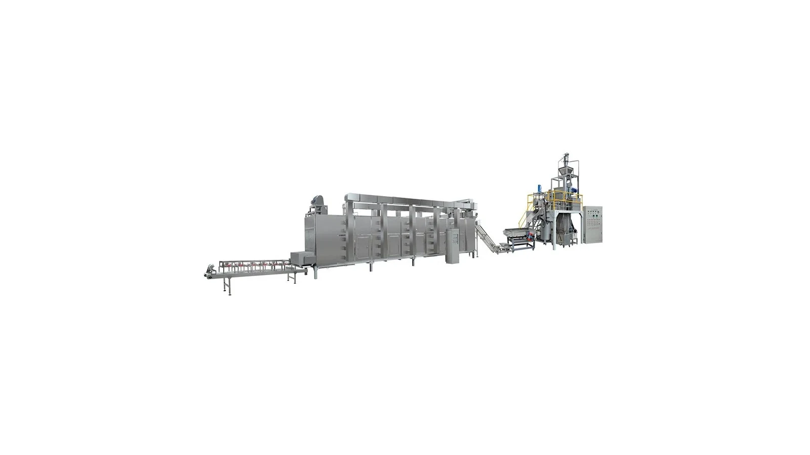
Freeze the Process Boundary First
List every stage in scope and identify who supplies it. Include raw-material receiving, storage, dosing or preparation, mixing, transfer, extrusion, cutting, drying, cooling, packing, finished-goods staging, and waste or rework handling where applicable. Mark interfaces to any buyer-supplied system.
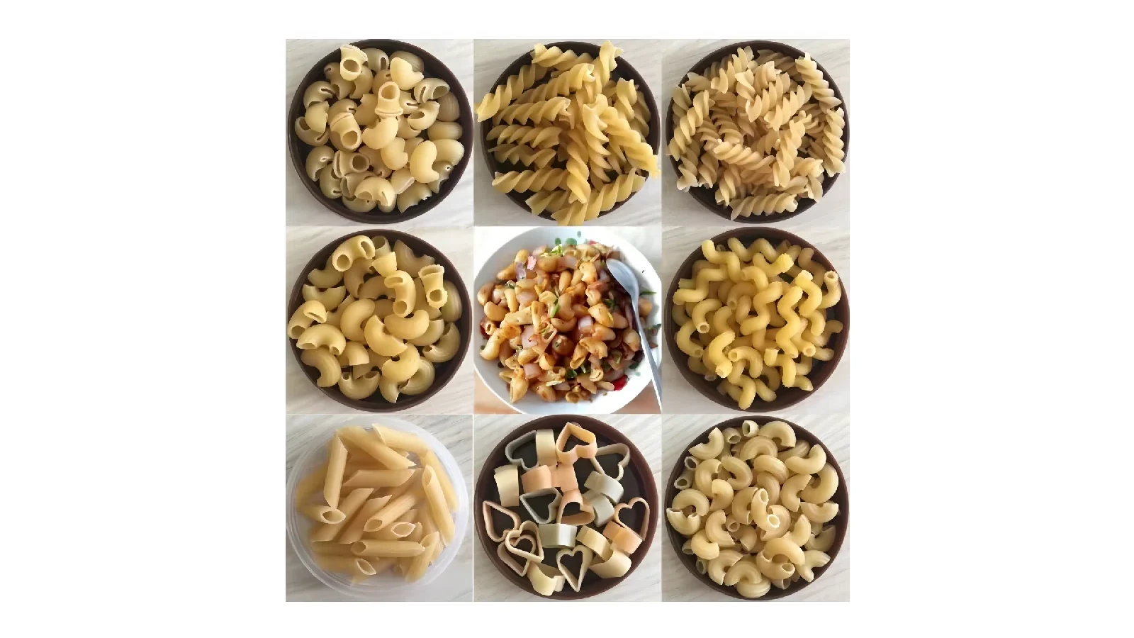
Add the target shapes and the production route for each shape family. Product decisions affect molds, cutters, drying review, transfer, and packing. The industrial macaroni line capacity guide can help define the output class, but capacity selection alone cannot determine the building arrangement.
Give the process diagram a revision number. A line drawn before the packing boundary or dryer configuration is agreed should remain clearly marked as preliminary.
Survey the Building in Three Dimensions
Provide a scaled floor plan with internal length and width, column locations, wall openings, door sizes, floor level changes, pits, drains, and fixed services. Add a section drawing that shows clear ceiling height, beams, roof trusses, mezzanines, and any overhead crane or lifting restriction.
Vertical space matters around elevated feeders, silos, conveyors, platforms, ductwork, and dryer services. Record the lowest obstruction, not only the nominal roof height. Where equipment may pass under a beam during installation, show both the operating height and the rigging envelope.
Document the floor information available from the building engineer, including slab condition and any restricted loading zones. Final foundations, anchors, and structural approval belong to the qualified parties responsible for the selected equipment and site.
Draw Material, People, and Finished-Product Flow
Use separate arrows for ingredients, packaging materials, operators, maintenance access, finished product, and waste or rejected material. The purpose is to reveal crossings and blind transfers, not to decorate the plan. Show storage and staging areas with realistic access for the site's chosen handling method.
Ingredient movement should reach preparation and mixing without blocking finished-product traffic. The dryer discharge and cooling route should lead toward packing with an identified buffer or transfer strategy. Finished packs need a defined path to case handling and storage. Personnel doors, emergency routes, and local safety requirements remain part of the site's qualified design review.
Reserve Service and Cleaning Access
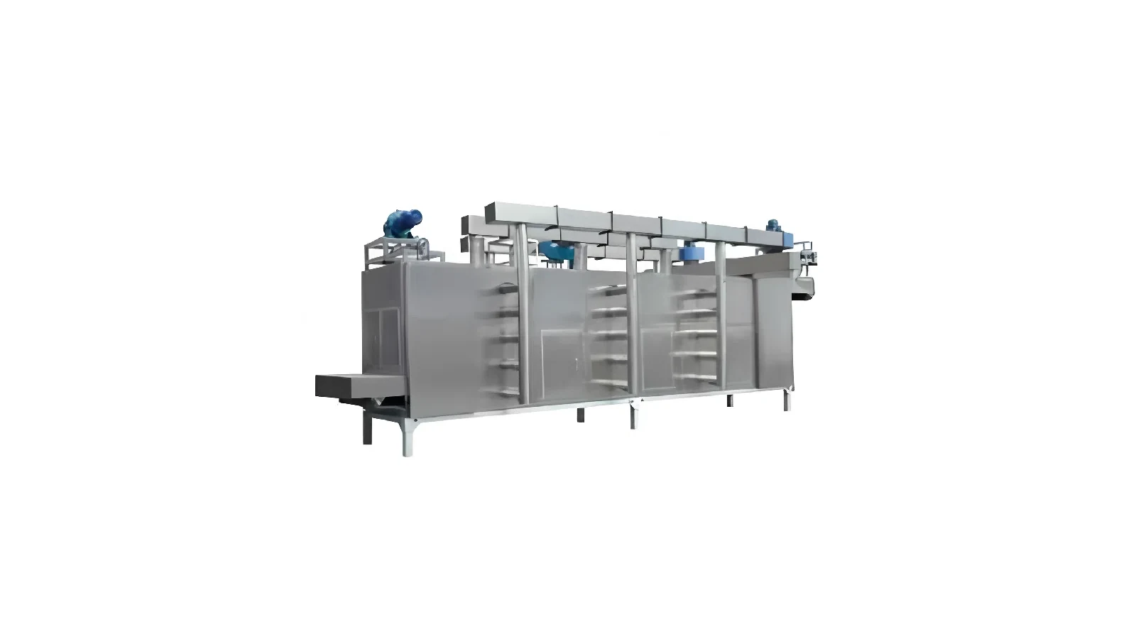
Draw maintenance envelopes around motors, gearboxes, covers, cutters, dies, screw-removal directions, dryer doors, fans, conveyors, electrical cabinets, and platform stairs. Ask which components need lifting space and which panels require full door swing. A narrow passage may look acceptable in a sales layout yet prevent routine access.
Mark product-contact inspection points and the routes used to remove parts for cleaning or changeover. Record nearby wash, collection, or tool areas only when they belong to the buyer's approved process. Exact sanitation design and procedures depend on the product, configuration, buyer policy, and applicable requirements.
The supplier drawing should distinguish operator standing space from deeper maintenance space. That distinction helps the buyer protect critical clearances during later building changes.
Build a Utility Interface Schedule
Create one numbered connection schedule tied to the layout. Include the site's voltage, phase, frequency, available electrical distribution, water conditions, drainage, compressed air, ventilation or exhaust, and any thermal service that the proposed configuration may require. Mark each connection point, routing responsibility, and isolation boundary.
Avoid copying a single machine's power into the complete-line plan. Extruder drive power is not the same as total connected load. The final schedule needs the selected mixer, feeder, conveyors, extruder, cutter, dryer, cooler, packing scope, controls, and auxiliaries.
Place panels where operators can see and reach them while preserving required access and site rules. Cable trays, pipe routes, valves, and drains should appear on coordinated drawings rather than being solved after delivery.
Plan the Delivery and Rigging Route
Trace the route from the site gate to each final equipment position. Record gate width and height, loading area, dock or floor level, doorway dimensions, corridor turns, column spacing, floor transitions, lift capacity, and overhead obstructions. Identify equipment that may arrive in modules and the space needed for assembly.
The buyer and supplier should agree which party provides unloading, internal movement, lifting equipment, temporary openings, foundations, anchors, and final positioning. Confirm these responsibilities in the commercial and technical documents. A clear rigging plan reduces the risk of discovering that a major section cannot reach its intended location.
Review Dryer and Packing Boundaries Together
The dryer often dominates floor area, vertical clearance, service access, and utility routing. Its inlet and outlet elevations need to align with upstream and downstream transfer equipment. Cooling and packing also require enough product handling space to avoid an undefined gap after the dryer.
Record the product condition expected at each handoff and show any buffer location. The exact residence time, moisture targets, cooling period, and packing rate stay tied to representative product trials and the chosen line. A layout drawing cannot guarantee product performance.
Control the Drawing Approval
Use a comment register with drawing number, revision, date, owner, question, response, and closeout status. At minimum, review process direction, equipment tags, dimensions, elevations, access envelopes, utility points, control boundaries, delivery route, and buyer-supplied work.
Freeze the approved layout only after the configuration and major interfaces are aligned. Later changes should show their impact on utilities, foundations, access, and schedule. Keep the approved drawing with the purchase scope so installation teams are not working from an early sales sketch.
Related Planning Guides
- Define the upstream zone with the industrial macaroni mixing and feeding brief.
- Reserve the major process section with the industrial pasta drying guide.
- Complete the downstream route with the macaroni cooling and packing handoff checklist.
Prepare the Layout Review
Send target shapes, material route, output class, building drawings, door and ceiling dimensions, utility conditions, packing boundary and destination for a layout review.